Monday 18 August 2008

Free Vray scene files for download

On September 3rd and 4th, there will be a two day Vray for Rhino training session at RhinoCentre. In this beginning to intermediate course, you will be guided through Vray to get you started with this versatile rendering plugin for Rhino.
For more information about this course, look here.
As a warm up, I have made two files available for download, which you can render with Vray for Rhino SR1. Maps and materials are included. These two examples clearly show how you can turn relatively simple scenes into convincing photo realistic imagery.

Grab the bathroom scene file here.
Grab the phone scene file here.

If you don't have a copy of Vray, you can download a demo version from the ASGVis website.


The bathroom model shows how a photographic atmosphere can be created by combining various light types. As you can see the model is very simple as well as the materials. In this case the lighting is the most important factor in the overall image quality. The scene file looks like this in your Rhino viewport:

And this is the resulting rendering:

The phone model shows how one can mix different material properties in one material using masks. Furthermore it does not use any lightsources. The lighting and reflections are controlled by a set of 2 HDRI maps: a blurry one for the lighting, and a sharp one for the reflections.
The scene file looks like this in your Rhino viewport:

And this is the resulting rendering:

Tuesday 10 June 2008

Joining Edges

Chances are you've never bothered about joining and exploding surfaces. In this short article I show what Rhino does when joining edges automatically and possible issues when working with exploded polysurfaces.

To see what happens when joining surfaces let's take a look at this exaggerated example. We have two surfaces that have no edges that match up, but we can force to join them with the JoinEdge command. (You can download the example file)


When we do this, Rhino will of course ask if we are really sure about this action, since the edges are way out of tolerance in order to join them.

Still we choose yes. Now it becomes apparent what is happening. The mesh is now closed, we can not see through the gap that was originally there. But the wireframe of the two surfaces shows something more. One of the edges has been transformed to the edge it was joined to.

Now you might think that after exploding, the edge is put back into its original position. But this is not the case as can be seen in the following image. For clarity, the surfaces have been moved apart.

You can probably guess now what happens if you start building new geometry based on these exploded surfaces. As you can see for yourself, you can still snap to the original edge end, but to the transformed edge end as well. Of course it is not difficult in this case to pick the right end, but in normal file, you will not notice which end you select.

Fortunately Rhino has a command to clean up these transformed edges with the command RebuildEdges. This will rebuild edge to match the original edge within the tolerance specified in the command.

Friday 9 May 2008

Rhino System Requirements


The first IBM PC
What's a reasonable workstation to run Rhino on? How can I get the most bang for the buck?
These are all valid questions and hard to answer. Not only because the world is changing fast when it comes to computer hardware. Another important factor is whether you use Rhino mainly for modeling or also for advanced rendering?
SimplyRhino, my English Rhino reseller colleague, offers a nice service to their customers.
At the moment I am very happy with a Dell Precision Laptop with 17" WUXGA screen. Together with Windows XP and a NVidia Quadro graphics card it runs Rhino very well. With a docking station and extra 24" screen I use it as my desktop too.
No Vista for me as it consumes a lot of computer resources which are now available for Rhino!
Dutch Rhino users can order Dell computers with a discount via RhinoCentre.

Wednesday 7 May 2008

Shed more light on Rhino


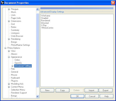
  • Install the RhinoCentre.ini files in Rhino via menu: File/Properties/Appearance/ Advanced settings/ Import
  • Tune the improved displays yourself if you like by clicking: +Advanced Settings
  • Please send me your improved .ini files and comments.


Learn more below
.

Default Rhino Shaded Display

Every now and then I discover that I take some features of Rhino for granted and cope with them for several years until I find out that it is far from optimal. Shaded display mode for example is my default perspective view for years now and there's always a voice in my head whispering that it is strange that symmetrical models, ship hulls for example, show better from one side. As a result of this I keep rotating the view over and over again in order to see what the surface quality is. When you look at the picture above you witness that the scene is too dark and parts of the hull are nearly invisible. I even should start modeling the starboard side of the hull to be able to evaluate the surface quality and mirror this after I am satisfied with the result. Isn't that strange?
Gijs de Zwart explained to me that the lights creating the shaded display are not optimal and I started a little investigation which resulted in the following:


RhinoCentre Display

First of all I can tell that it took me hours to come to this result and I am not satisfied yet. There are so many constraints from a functional point of view that the Rhino default shaded display proves to be a Jack of all trades, master of none, though ofttimes better than master of one.

When you think you have set it all right for one purpose it proves worse for others. Anyway, I learned a lot. Do you understand why black is shown grey in Rhino? I found out that black should be displayed white actually! Due to a lack of light it looks grey.
Rhino's default layer is always black which results in black curves. On the other hand, surfaces in the default layer and other 'black' layers, are displayed white which shows grey in shaded display mode due to a lack of light, and only glossy areas will show in pure white. Do you still follow me?
From a functional point of view I understand that designers used to draw nearly black lines with their pencils on paper which resulted in white surfaces inside the contours. Maybe that's the reason that Rhino inverts black into white for surface display. Another reason for the grey display of black surfaces is that the curvature is hard to see when surfaces are displayed black.
To see really black objects, please try the following. As a black layer contains Red/Green/Blue values of 0/0/0 which show grey (instead of white), you should set RGB values to 1/1/1 and it shows better black. Lack of light is also the reason that white coloured surfaces show grey too. Therefore it is important to add more light to the scene.


Left: Rhino default lights .............Right: RhinoCentre lights

Furthermore it is important to balance the light and enlighten the total scene evenly to have the same display, with mirrored parts for example. The risk of adding light is that surfaces are over-exposed and you cannot see the shape and depth anymore. Furthermore you can add a little color to the light in order to see differences between adjacent surfaces of the same color, especially white surfaces.
What's the difference between the default shading and RhinoCentre's display?
In the picture above you can see that the default lights for the shader are not located evenly in the scene causing differences between mirrored parts. There are actually only three lights in the Rhino shader. Adding light and position them evenly makes a difference.
What actually is the case is that the lights of the shader are dynamic and always maintain the same position and orientation relative to the camera view. The position of the lights in the picture above corresponds with a camera position in front of the bow.


Black and white

Furthermore, white is now white instead of grey due to more light at the scene. Rhino's default lights result in under-exposure. More lights are added and calibrated to black and white objects. Black will be black when RGB is set to 1/1/1. At last a little color is added to the lights to add more depth to the scene and not only depend on brightness.
Time will tell whether it is annoying to see white surfaces appear with a little color under certain angles.

Another thing is the choice for surface edge display. It is tempting to switch edge display off and I admit that it looks sometimes better. On the other hand it proves to be very functional to see surface borders during modeling.

The last issue is the background color. Grey seems boring but doesn't radiate too much light in comparison to white, and your eyes get less tired. Black, or near black, on the other hand is another cool option. For recognition I choose for grey, especially when a design contains only a few surfaces you avoid constantly looking into a 'black hole'.

Friday 2 May 2008

Vray for Rhino SR1 out soon

V-Ray for Rhino, being developed by ASGVis, is one of the integrated rendering solutions available today. The upcoming service release for Rhino 4 is an important step forward in terms of productivity. A lot of bugs from the 1.00 version are ironed out, gamma correction is much easier to work with and last but not least, distributed rendering is now very easy to setup and use. Furthermore, SR1 will include support for IES lights. SR1 will now search sub folders automatically in case of missing maps. This will make the process of sharing scenes and materials a lot easier.


SR1 will have a new licensing system with a license server. This makes V-Ray more usable in larger studio's, since licenses can be shared and administered from a single location.

By the end of this year V-Ray for Rhino will adapt more of the features that are currently available in the 3dsmax version of V-Ray. There will be toon rendering, ambient occlusion and progressive real time rendering preview, which will aid in setting up a final rendering without having to make numerous test renderings.
In terms of interconnectivity, there is more to look forward to. Especially large studio's will benefit from material and scene exchange between packages. ASGVis's material format .vismat and V-Ray's .vrmesh will make it possible to let (parts of) scenes be created in Rhino and be rendered in 3dsmax or vice versa!

Friday 11 April 2008

Guest editor: Gijs de Zwart

Gijs de Zwart is a landmark as it comes to Rhino visualisation, therefore I am very proud to announce that he will be guest editor at this blog. Furthermore he will co-operate with the RhinoCentre as a visualisation specialist offering several services.


For more info about the Studio Quality Rendering Tutorial, click on the picture
Most people know Gijs from his Studio Quality Rendering Tutorial for Flamingo he made a few years ago. Since then he developed himself into rendering with V-Ray for Rhino and has a good relation with ASGVIS as a beta tester. ASGVIS is the company behind V-Ray for Rhino.

V-Ray image by Gijs de Zwart
Being a specialist in visualisation he will share some of his experiences and knowledge at this blog. Furthermore he will offer visualisation class training at RhinoCentre in the near future.
Please take a look at his company website, StudioGijs, if you like to know more about his competences.
Related links:

Friday 21 March 2008

Explicit History Plugin for visual scripting

Click on the screenshot to see a demo I made
(play with it yourself and download the demo files below)

Most designers have a visual perception of the world, which makes Rhino a superb tool to present and visualise ideas and designs. Furthermore the user interface of Rhino is quite visual oriented if you compare it to older CAD software.
One feature of Rhino though isn't visual at all, it's called scripting. To make use of scripts, you have to write a program (code) which can be executed in order to generate geometry in Rhino.
Why script? With these 'little' and 'custom' programs designers make clever use of Rhino in order to make fast design variations, or create smart repetitive design elements. Another application of scripting is to solve technical features based on parameters which influence the form, position or orientation of geometry.


Rhino facade script for UN Studio's Light*house Aarhus Harbor Front
Image courtesy 3XN and UNStudio

Leading architects, for example, use scripts more and more to be able to design stunning and functional architecture. This is quite an achievement as they have to switch to another mindset in order to program their scripts instead of modeling surfaces straight away.
David Rutten of McNeel & Associates, the company behind Rhino, developed a new way to create scripts for Rhino on a visual basis. After David created the Monkey Script Editor to make scripting for Rhino more easy, he created the Explicit History Plug In which brings scripting to designers even better!

If this plugin doesn't make you script, you probably never will!

As the Explicit History Plugin is full under development you can try it out for free and help David to develop it even better. Read more and download a free work in progress version to try it out yourself:

Monday 14 January 2008

Tolerance Settings in Rhino; a little survey

What's really the influence of tolerance settings when modeling in Rhino?
For investigation I took the default 10 meter long sailboat hull from the Rhinomarine hull modeling module. This is a very clean hull with only few control points as you can see yourself.
The filesize of this hull is 60 kb with Save Small (without render meshes).

Certain operations in Rhino depend on the user tolerance. Examples of geometry build to tolerance are: intersections between two surfaces, section curves, offset curves and surfaces, curves projected onto surfaces. These types of geometry are constructed by refinement methods that stop refining when it is within tolerance. Many other operations build geometry to a much greater accuracy. For instance the intersection of 2 lines that are on the same plane will be much more accurate (thank you Jim).
To find and change the tolerance settings open the menu: File/ Properties/ Units. Default values for large objects can be:
- Units: Millimeters
- Absolute Tolerance: 0.01 units (mm)

Then I created two sections:
1- Tolerance set to 1.00 mm. resulted in the red line based on 14 control points
2- Tolerance set to 0.01 mm. resulted in the blue line based on 226 control points
The maximum deviation between the two curves is 0.168406 mm. Find this command under menu: Analye/ Curve/ Deviation

Next I saved each curve including the hull into two separate files which resulted in:
1- 61 kb file for the 1.00 mm. tolerance curve + hull
2- 68 kb file for the 0.01 mm. tolerance curve + hull
The difference in filesize is 10% (Save Small).


After making a frame surface based on the section the difference in filesize is:
1- 66 kb for a single frame surface (+ hull) based on the 1.00 mm. tolerance
2- 103 kb for a single frame surface (+ hull) based on the 0.01 mm. tolerance
The difference increases to 36%.


At last a solid frame is made with a certain thickness which increases the filesize even more:
1- 80 kb for a single solid frame and hull (1.00 mm. tolerance).
2- 174 kb for a single solid frame and hull (0.01 mm. tolerance).
Resulting in a more than 2 times bigger file for the 0.01 mm. tolerance frame.

Why not model in centimeter or meters?
This is worth considering but as millimeters is the standard in a lot of industries, most people think in mill and AutoCAD drawings are also often in mm. Even with large products like ships and architecture I found out it is confusing to start modeling in meters and scale Acad drawings for input over and over again.

My conclusions are:
- tolerance settings can have a big impact to file size
- the impact gets bigger if 3d models are detailed up to solids
- deviation between the two analysed situations is a very little 0.168406 mm

Recommendation:
- depending on manufacturing techniques and accuracies, 0.5 or 1mm. absolute tolerance seems to be worth to consider with large and detailed 3d models such as ships, yachts and architecture

Some related commands:
- Rebuild; investigate the amount of control points and rebuild curves with less control points
- FitCrv; fit a curve to certain tolerance to the original object
- CrvDeviation; to measure the maximum deviation between two curves

You can download the file yourself over here

Tuesday 8 January 2008

Rhino Math; a little secret


For those interesting in geometry based on mathematics, this little plug in does the job.
Jess Maertterer developed it years ago and fortunately he shares it for free via his website.

Architectural application of this plug in is very interesting as several Universities have shown nice examples of geometry created with Rhino Math.


With this plug in you can create curves and surfaces based on mathematics, like x ^ y and x + y, but also Sin/Cos and Tan are covered. Furthermore the plug in offers a library with basic examples.

Download the plug in over here: http://www.rhino3.de/_develop/__v3_plugins/math/


For me it was a splendid solution to create hyperbolic golden ratio vortexes for my Schauberger research. This resulted in a design of a flying saucer based on cold fusion physics.

Ifo - identified flying object