More than a decade ago, naval architect and RhinoCentre founder Gerard Petersen, developed the "Hull Design and Fairing training for Rhino". In the development of this training, which started in 2012, he was supported by maritime Rhino specialists Tobias Nagel and Bas Goris.
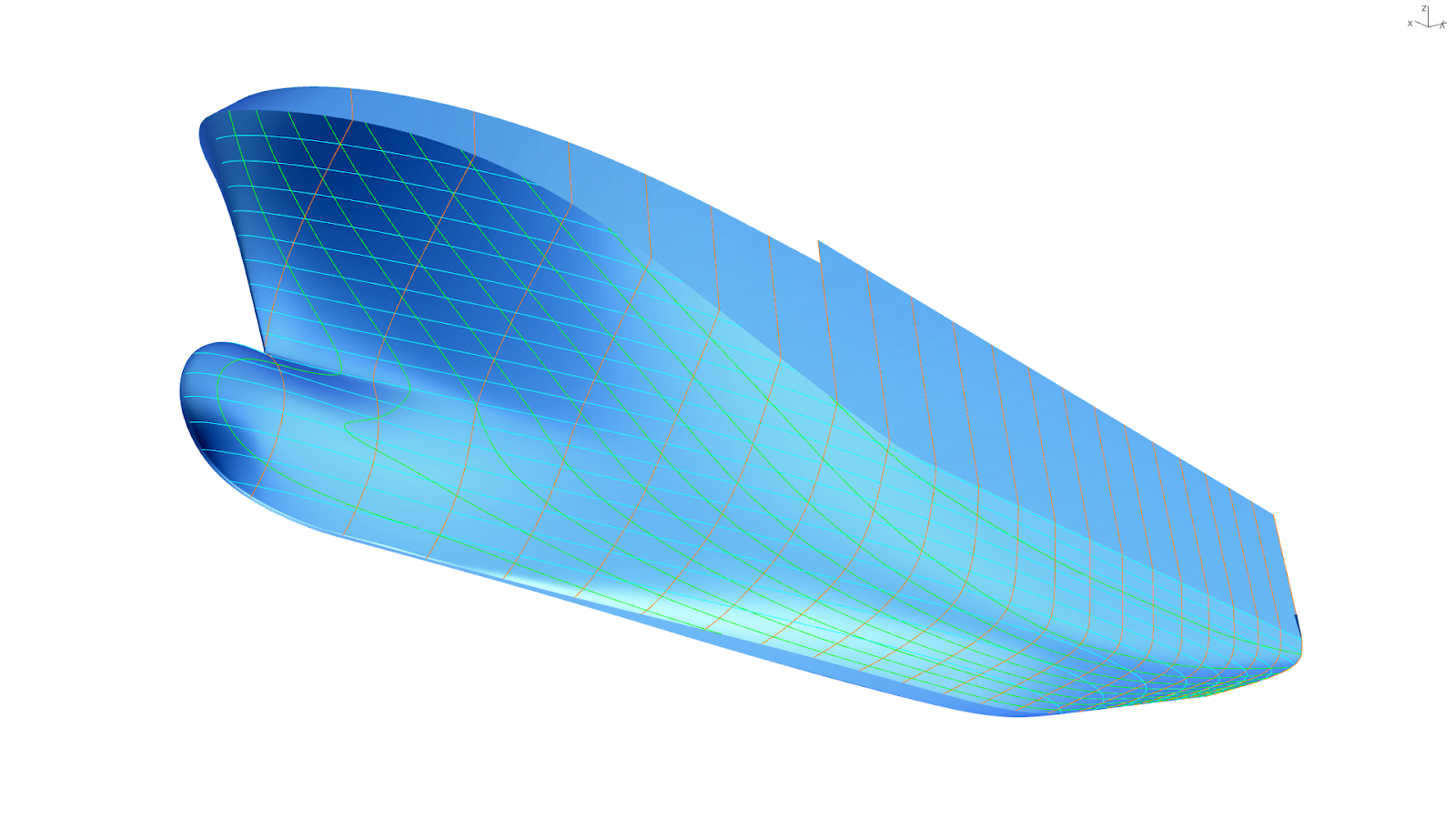
The aim for this training, was to teach the industry about the following themes: Class-A Fairing – Final Design – Fairing for Production – Hull Optimization – Reverse Engineering – Hull from GA/ Lines-Plan – Advanced Analysis – Modeling Strategies – Developable Hulls
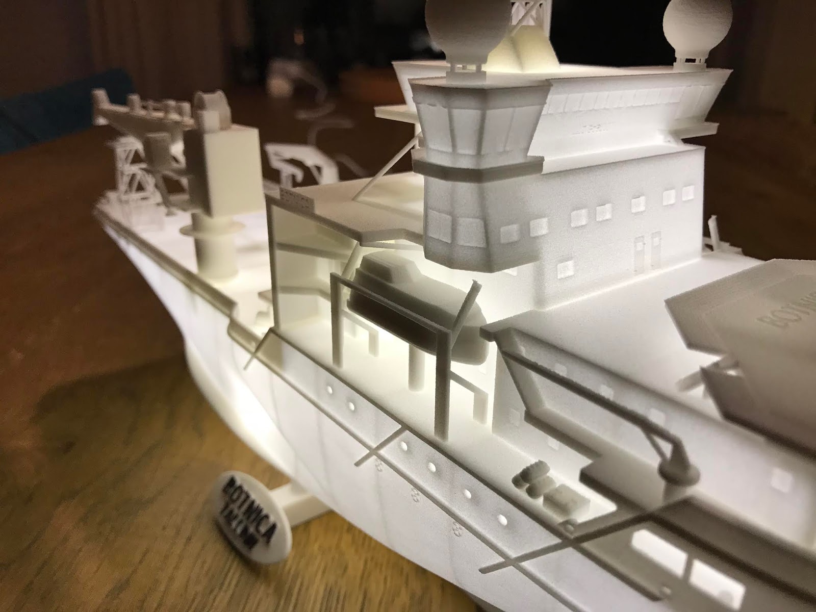
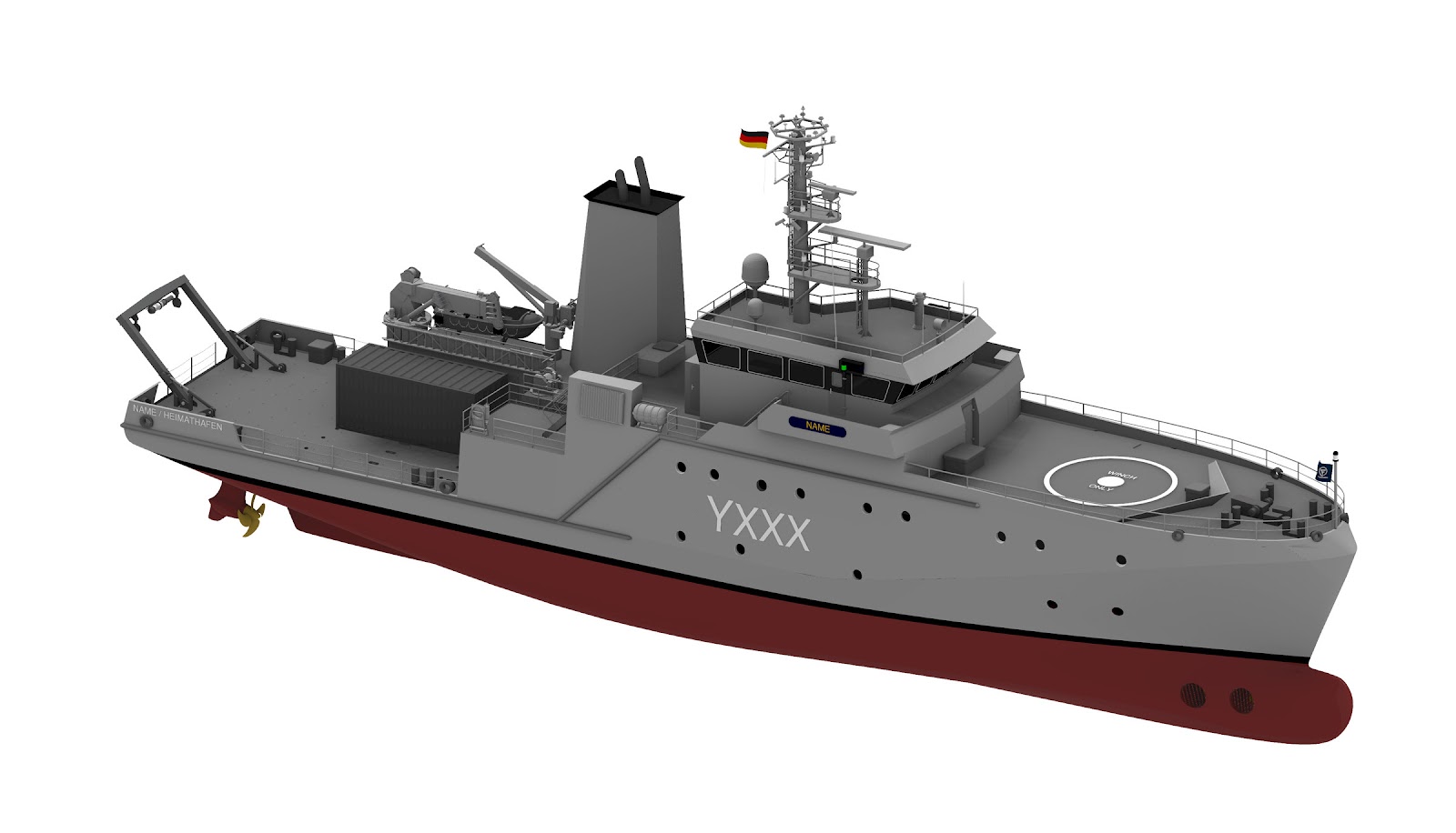
The learned lessons have to be applicable to a wide variety of types of vessel hulls of Ships, Yachts, Workboats and Multihulls. More than 10 years later, we can conclude that this has been successful as many vessels since then have been designed, engineered and manufactured based on the teachings.
The development of the training lead to three training modules, that were carefully published in three booklets:
- Grasshopper scripts for a parametric hull shape
- SubD modeling
- 5-degree 'Direct Surface Modeling'
- Projects for fine fairing and reverse engineering
- etc.

- Gusto MSC - NOV (Netherlands)
- General Dynamics Nassco (USA)
- BMT Defence & Security (UK)
- FR. Fassmer GmbH & Co. KG (Germany)
- Austal Ships (Australia)
- Bureau Veritas Croatia
- Astilleros y Varaderos Lago Abeijón (Spain)
- Knud E. Hansen (Denmark)
- Lungteh Shipbuilding Co.Ltd (Taiwan)
- Bollinger Shipyards (USA)
- Damen Schelde Naval Shipbuilding (Netherlands)
- Sause Bros. (USA)
- Baku Shipyard LLC (Azebaijan)
- Sorgiovanni Designs (Australia)
- Profjord (Sweden)
- OSK-ShipTech A/S (Denmark)
- 7Waves (Norway)
- SEDS (India)
- Odense Maritime (Denmark)
- Spliethoff’s Bevrachtingskantoor B.V (Netherlands)
- Fisheries and Oceans Canada
- Serco Canada Marine
- Kongsberg Maritime (Norway)
- VPLP design Paris (France)